
Impact profile
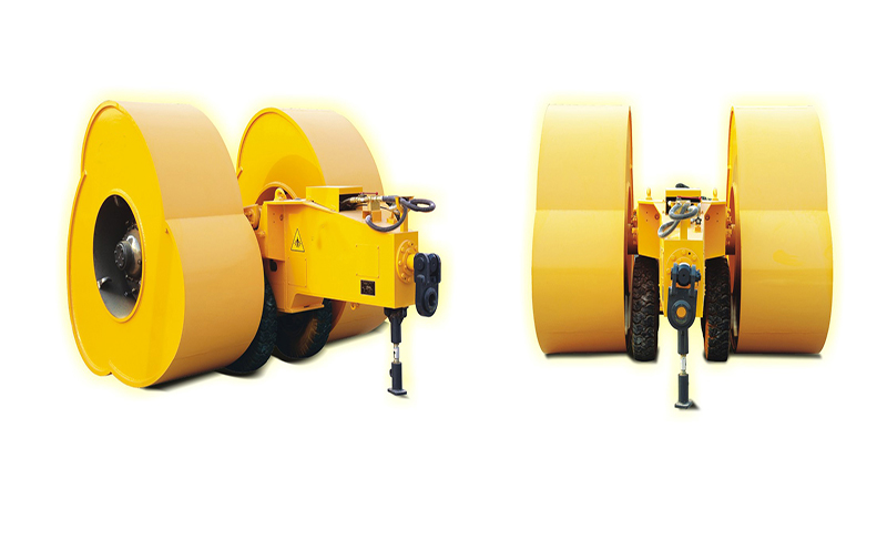
A 3-sided roller and a 5-sided roller provide different polygonal contact sequences. Geometry is reviewed with energy class, travel speed, route and material response.
Polygonal roller geometry guide
A 3-sided or 5-sided impact roller changes the number of impacts and the working profile along a route. The choice belongs in a complete working-system review, not a simple geometry ranking.
Use this page to prepare the site inputs CMG needs before discussing roller geometry, energy class and tow configuration.
Ask about this topic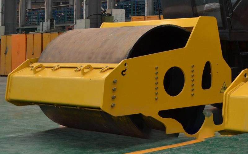
Guide contents
A 3-sided roller and a 5-sided roller provide different polygonal contact sequences. Geometry is reviewed with energy class, travel speed, route and material response.
Working area, turning space, access, available tow equipment and programme determine whether a geometry can be operated safely and practically.
CMG currently publishes source-matched technical data for the 32 kJ and 35 kJ impact roller pages. Other geometry or model combinations remain selection-led until a matching source is approved.
Geometry does not define project acceptance. The project inspection or testing route remains the final acceptance authority.
Evidence boundary
CMG uses this resource to organise a project conversation. It does not replace site investigation, geotechnical design, equipment documentation or the project acceptance specification.
Buyer checklist
Decision record
Use the following record as a handover between procurement, site engineering and the equipment supplier. Empty fields are signals to investigate, not assumptions to fill with a generic machine claim.
Related equipment
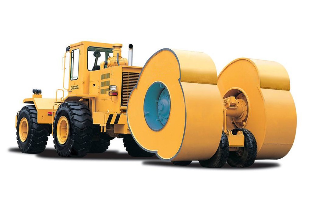
High-energy polygonal roller for demanding subgrade and ground improvement projects.
Explore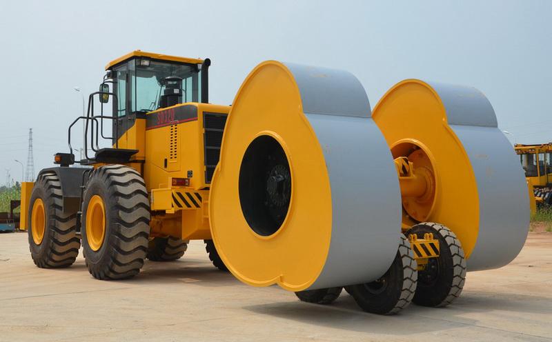
A high-energy impact roller for embankment, subgrade and foundation treatment.
Explore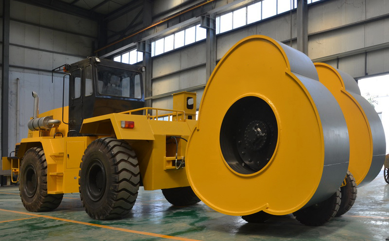
Balanced high-energy compaction for road base, fill and infrastructure construction.
Explore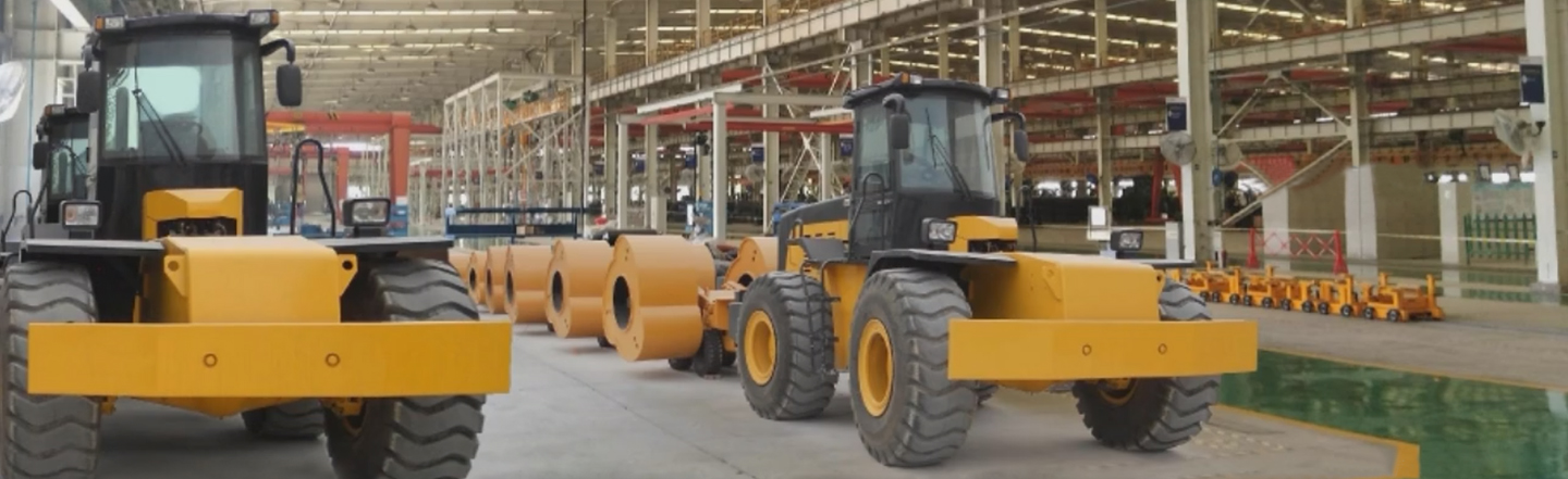
Video centre
Review available CMG equipment footage, then bring your project inputs to the technical discussion.
Visit the CMG video centreResource FAQ
The working profile and impact sequence differ. The suitable geometry is reviewed with energy, speed, route, tow equipment and material response.
No. Geometry selection depends on the working system and site conditions.
The CMG 32 kJ and 35 kJ pages publish source-matched technical parameters. Other combinations remain selection-led.
Through project planning and the specified inspection or testing route.